
Purpose: Wire the store network the recommended way and connect a POS station (POS machine, receipt printer, card terminal, cash drawer, customer display). For: Adoluna onboarding staff, store managers. Hardware: see 3.1.1 What hardware you need (supported devices list).
Network plan #
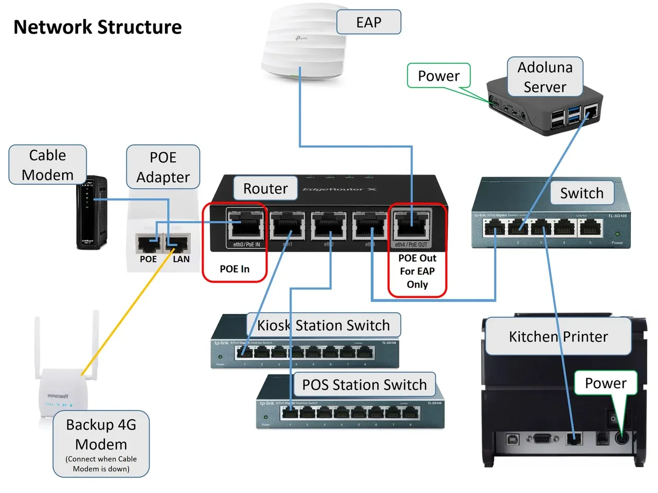
_Figure: store network structure (official website doc image). It shows an older setup: an EdgeRouter X router plus a PoE adapter and a backup 4G modem. The GL.iNet GL-MT6000 (Flint 2) is now recommended; see steps 3 and 4 below._
1. The router must stay online at all times. Adoluna POS runs in the cloud, and needs the internet even to take orders: when the store’s internet is down, the whole POS stops working. You can’t take orders, print or take cash (the cash drawer won’t open), and card payments, online orders and third-party orders all stop too (see 4.4.1 What to do when the Local Server is offline).
2. The Adoluna Local Server, receipt printers and card terminals must be on the same network.
3. Wiring: cable modem → router; the router’s ports go to the POS station switch, the Kiosk station switch and the switch that connects the Local Server and kitchen printer. The recommended router is the GL.iNet GL-MT6000 (Flint 2), and the recommended switch is the TP-Link TL-SG105 (5-port) or TL-SG108 (8-port). Large restaurants add TP-Link EAP access points, connected to the router by Ethernet.
4. Backup internet: the Flint 2 can use a phone hotspot as a backup connection, so the store stays online when the line is down. The PoE adapter and backup 4G modem in the diagram are no longer recommended.
Wire a POS station #
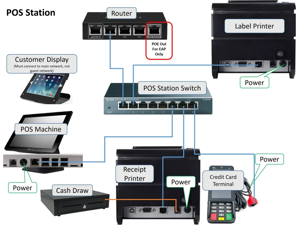
Figure: POS station wiring (official website doc image)
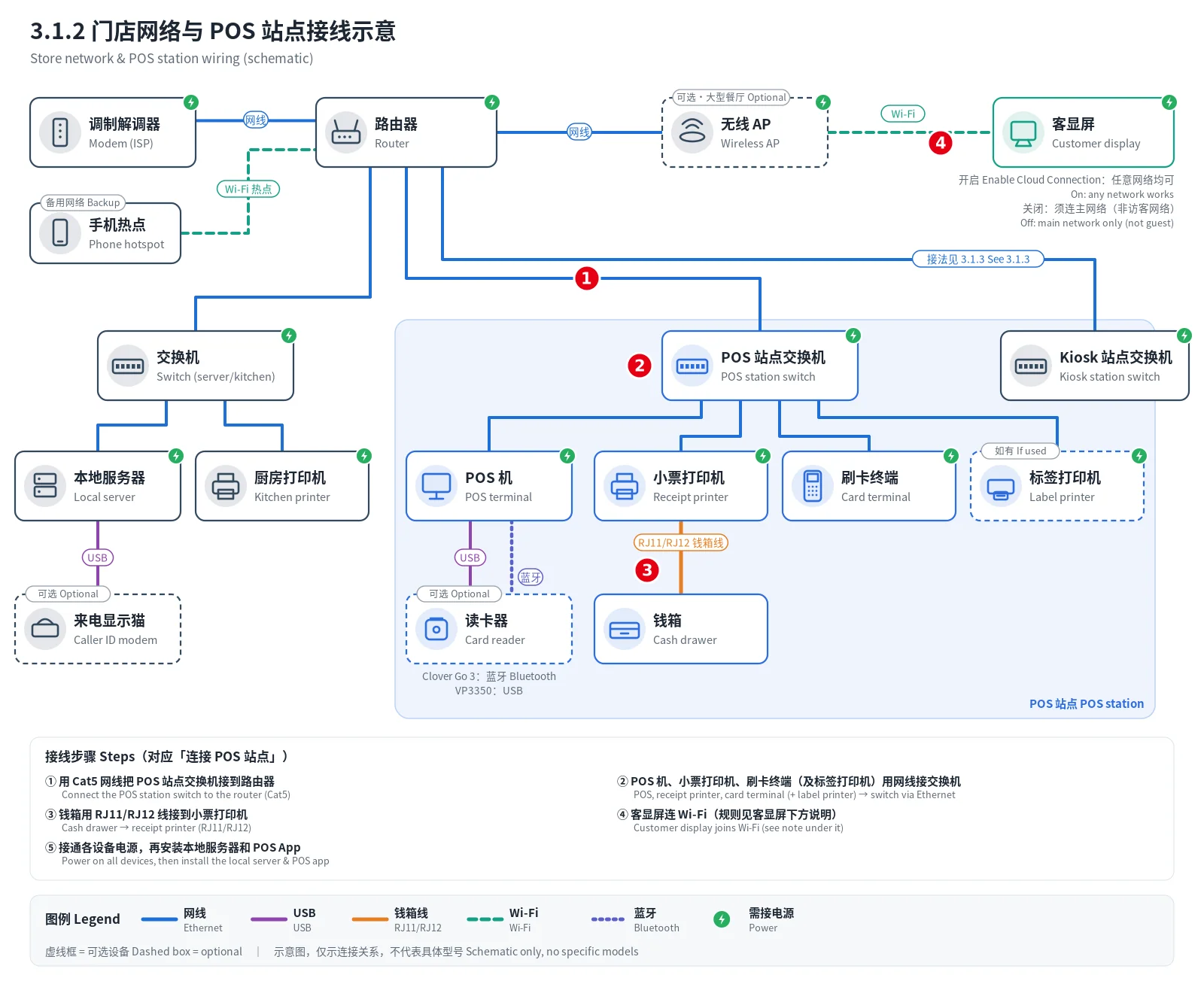
Figure: store network and POS station wiring diagram (drawn 2026-10-05). ①–⑤ match steps 1–5 below; dashed boxes are optional devices.
1. Connect the POS station switch to the router with an Ethernet cable (Cat 5).
2. Connect the POS machine, receipt printer and card terminal (and label printer, if any) to the switch with Ethernet cables.
3. Connect the cash drawer to the receipt printer with an RJ11/RJ12 data cable.
4. The customer display connects over WiFi: to the access point’s WiFi if there is one, otherwise to the router’s WiFi. With Enable Cloud Connection on in that POS’s customer display settings in the Backoffice, the display connects through the cloud: it doesn’t need to be on the same network as the POS and Local Server, and doesn’t depend on the Local Server. With it off, the display goes through the Local Server; then, as the website diagram says, it must be on the main network (not the guest network) and on the same network as the POS and Local Server. See 3.5.1 How to set up the customer display, 4.4.2 What to do when the customer display won’t connect.
5. Plug in the power and turn everything on. Then set up the Local Server (3.2.5 How to set up the Adoluna Local Server) and install Adoluna POS (3.2.1 How to install Adoluna POS on each platform).
Notes / FAQ #
-
Printers, card terminals, the Local Server and other devices need fixed IPs: reserve their addresses in the router (DHCP reservation) and also set a fixed IP on each device itself. Printer IP setup is in 3.3.2 How to print a config page and change a printer’s IP.
-
When done, check every cable is seated and each port matches the diagram.


